

Results 1 to 15 of 17
Thread: Terrain and Contours questions
-
07-19-2006, 04:17 AM #1
 Registered User Promoted
- Join Date
- Jan 2005
- Posts
- 196
Terrain and Contours questions
Terrain and Contours
Hi Everyone,
Is there a way to manually draw in the contours rather than have CA do them for me? I tried using the Elevation Spline and Elevation Line Tools to put in the contours that I want for the model, but CA keeps making new contour lines even though I have "Auto Calculate Elevation" turned off in the Terrain Specifications DBX. Is there some other box that I need to uncheck?
I would rather be able to control the contours on my projects than have CA do it for me in particular for landscaping features, drainage, etc.
Any help will be appreciated.
Richard E. Owen Jr.,
N.J. Registered Architect - N.J. Licensed Professional Planner
-
07-19-2006, 04:26 AM #2
Registered User Promoted
- Join Date
- Jan 2005
- Posts
- 196
Missing contour labels.
Hi Agian,
Also how do you turn on the contur labels? Mine are missing from the contours created.
Thanks
Dick Owen
-
07-19-2006, 04:40 AM #3
Registered User Promoted
- Join Date
- Aug 1999
- Posts
- 6,414
terrain dbx>contours tab....set the intervals value higher, set the frequency of primary contours to a higher number, then go to layerdisplay and turnoff the layer for terrain, secondary contours (you can also turn off the primary ones if you want)
Tim O'Donnell
-
07-19-2006, 04:42 AM #4
Registered User Promoted
- Join Date
- Jan 2005
- Posts
- 196
Thanks Tim,
I shall try your suggestions and let you know how it works for my project.
-
07-19-2006, 04:47 AM #5
Professional Chiefer
- Join Date
- Jul 2005
- Location
- Brownsburg, Indiana
- Posts
- 5,614
Hi Dick, I think as long as you put an elevation line at every 1' drop in elevation, Chief will not add additional lines. However, if you skip one and go two or three feet, Chief will add intermediate lines showing where each 12" drop is.
Allen Brown
Indy Blueprints
Residential & Commercial Designs & Drafting Service
V8-X4, Specializing in Plan Completion, Problem solving, & Chief Architect Training.
Free Chief Architect Training Videos:
www.IndyBlueprints.com
Need help on a plan? Or 1 on 1 instruction? Email or call.
www.UBuildItIndy.com
-
07-19-2006, 05:11 AM #6
Registered User Promoted
- Join Date
- Jan 2005
- Posts
- 196
Hi Tim,
I tried your suggestions and they will work, but not exactly what I wanted to do.
I am wondering can you let CA calculate the contours based on elevation lines or splines, then you can edit the contours and then lock them similar to what you can do with wall framing, roof planes, etc?
I can see the many benefits of having CA get me started with auto creating the contours based on eleavtion lines or elavation splines, and then being able to edit them to fit the project.
Also I am still having problems with the contour labels showing up. I looked at the layer display options and did not see anything that should be turned or was missing. How do you control the text size for the contours?
Again, your help is greatly appreciated. I have been reading this board for a while and your suggestions as well as from many others have been very helpful to me as I learn this program.
Thanks,
Dick
-
07-20-2006, 08:58 AM #7
Registered User Promoted
- Join Date
- Jan 2005
- Posts
- 196
Hi Allan,
Thanks for your help. I tried what you had suggested and it sort of works. How do I change the text size for the contour lines? I cannot not read them they are so small and I have been searching for a way to make them larger.
Also I would like to know are there any others on this board that would like to be able to edit the contours that CA creates and then be able to lock them similar to what we can do when we edit wall framing, roof plains, etc? I think that would be a great help to me since all the building Depts in my area require detailed grading plans.
Any comments and help will be appreciated.
Thanks
DIck Owen
-
07-20-2006, 09:06 AM #8
Registered User Promoted
- Join Date
- Apr 2004
- Location
- LOCKPORT NY
- Posts
- 18,655
Dick:
It would be best to post this in the suggestions sub-forum so that CA is sure to see it.
LewLew Buttery
Castle Golden Design - "We make dreams visible"
Lockport, NY
716-434-5051
www.castlegoldendesign.com
lbuttery at castlegoldendesign.com
CHIEF X5 (started with v9.5)
-
07-20-2006, 09:12 AM #9
Professional Chiefer
- Join Date
- Jul 2005
- Location
- Brownsburg, Indiana
- Posts
- 5,614
I have not figured out how to change the font size, but you could always add text of a larger size over it. I know...I know...not the dreaded work-around again
 Allen Brown
Indy Blueprints
Residential & Commercial Designs & Drafting Service
V8-X4, Specializing in Plan Completion, Problem solving, & Chief Architect Training.
Free Chief Architect Training Videos:
www.IndyBlueprints.com
Need help on a plan? Or 1 on 1 instruction? Email or call.
www.UBuildItIndy.com
-
07-20-2006, 09:34 AM #10
Registered User Promoted
- Join Date
- Jun 2001
- Location
- Houston,Texas
- Posts
- 10,154
The size on the screen is controled by the pixel setting in dimension defaults. The print size is controled by the label text size in the terrain dialog box.How do you control the text size for the contours?
-
07-20-2006, 09:52 AM #11
Professional Chiefer
- Join Date
- Jul 2005
- Location
- Brownsburg, Indiana
- Posts
- 5,614
Good call Louis,
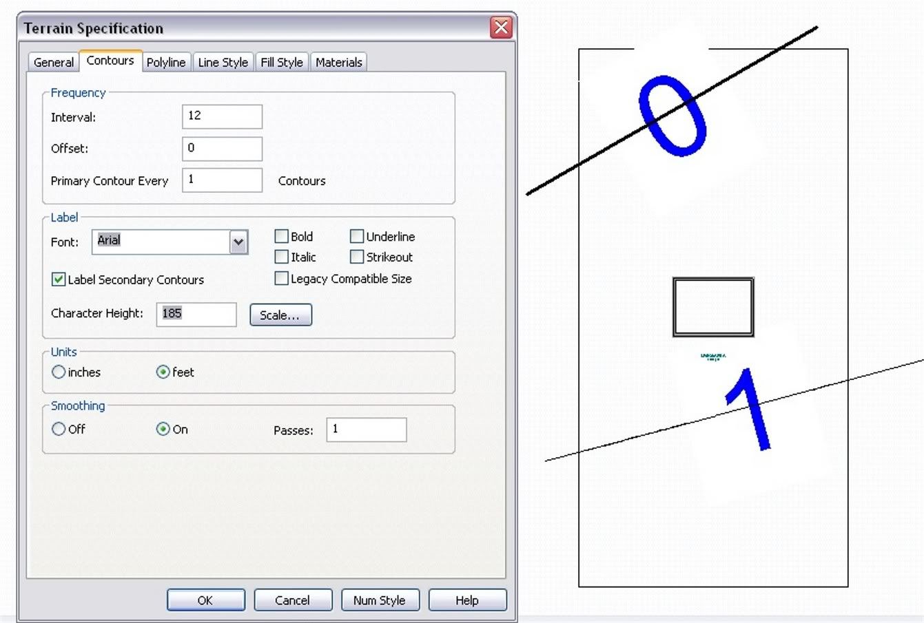
Double click on terrain tool, go to contours tab, set character height. Here it's set at 185:
 Allen Brown
Indy Blueprints
Residential & Commercial Designs & Drafting Service
V8-X4, Specializing in Plan Completion, Problem solving, & Chief Architect Training.
Free Chief Architect Training Videos:
www.IndyBlueprints.com
Need help on a plan? Or 1 on 1 instruction? Email or call.
www.UBuildItIndy.com
-
07-20-2006, 10:38 AM #12
Registered User Promoted
- Join Date
- Jun 2001
- Location
- Houston,Texas
- Posts
- 10,154
Allen,
I get paid to know this stuff.
-
07-20-2006, 12:53 PM #13
Registered User Promoted
- Join Date
- Jan 2005
- Posts
- 196
Thanks for all the suggestions.
Louis is that a feature in CA 10.08a? I am still on 9.54. I will perform the upgrade in the next day or so.
Again thanks to all who replied.
DicK Owen
-
07-20-2006, 01:05 PM #14
Registered User Promoted
- Join Date
- Aug 1999
- Location
- Ridgway, Colorado, USA
- Posts
- 2,917
Dick:Also I would like to know are there any others on this board that would like to be able to edit the contours that CA creates and then be able to lock them similar to what we can do when we edit wall framing, roof plains, etc? I think that would be a great help to me since all the building Depts in my area require detailed grading plans.
Any comments and help will be appreciated.
Yes. I would like an option to have the 3D grade go through contour lines so that the contour lines are where you place them...and stay there.
The problem is that Chief's terrain feature is intended to create 3D grades for images and is not really for civil engineering or accurate site grading. Basically what you are dealing with in Chief is:
The grade in section view works a little like a spline does. Elevation data influences the location of contour lines but the terrain does not necessarily go through the lines or points you place. This way you get the smother, more rounded, terrain in 3D views and not the sharp (linear) changes in grade.
My solution is to:
1. Add the elevation data (I use Elevation Lines most of the time) I need to create the terrain I need for 3D views.
2. Turn the elevation data layer and Chief contour line layers off in my site plan layer set and
3. Use CAD lines on layers I add for the site grading. In some cases I can use a copy of the "Elevation Lines" (that I used to create the terrain) for the proposed contour lines. Sounds a bit more complicated than it really is. Larry
Larry
Lawrence C. Kumpost, Architect
No matter how much you push the envelope, it'll still be
stationery.
-
07-21-2006, 07:27 AM #15
Registered User Promoted
- Join Date
- Jan 2005
- Posts
- 196
Hi Larry,
Thanks for the great suggestions. I will put the put a request as a future feature, once I learn where to submit it to, as Lew suggested.
Thanks
Dick Owen

 Reply With Quote


